This section describes the Apply Operator parameter used to generate a spectral blueing volume.
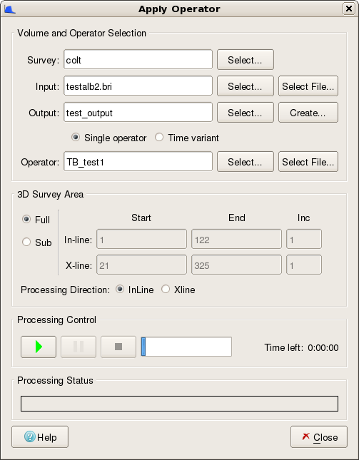
The Apply Operator dialog in SsbQt allows you to set up a processing run so that you can apply the spectral blueing operator generated during the analysis and design phase. The steps involved are briefly described below:
Select an input seismic survey (if run in an OpenWorks R5000 environment, but if run in a 2003.12 environment this input item will not exist). This step is initiated by clicking the push button to the right of the Input field. This action pops up another dialog which enables you to select the input survey from the current seismic database.
Select an input seismic volume. This step is initiated by clicking the push button to the right of the Input field. This action pops up another dialog which enables you to select the input volume from the current seismic database.
or
Select an input SEGY file. This step is initiated by clicking the push button to the right of the Input field. This action pops up a file selector dialog which allows you to choose a SEGY file from the file system.
Select an output seismic volume. This step is initiated by clicking the push button to the right of the Output field. This action pops up a separate dialog which enables you to select an existing output seismic volume.
or
Create a new output seismic volume. This step is initiated by clicking the push button to the right of the Output field. This action pops up a separate dialog which will enable you to create a new empty seismic volume. If this push button is labelled then a file selector dialog pops up allowing you to select a SEGY file to overwrite or to input a new SEGY file to create.
Check Single operator or Time variant radio button based on the operator you wish to apply on the seismic data. If Single operator radio button is checked then you can select an operator as mentioned in Step-5 . If Time variant radio button is checked then operator zones configured in Time Variant tab is applied on the seismic data and proceed to Step-6.
Select the spectral blueing operator from database, if Single operator radio button is checked. This step is initiated by clicking the push button to the right of the Operator field. This action pops up a separate dialog which enables you to select an operator stored in the database.
or
Select the spectral blueing operator from an ASCII file, if Single operator radio-button is checked. This step is initiated by clicking the push button to the right of the Operator field. This action pops up a file selector dialog allowing you to traverse the file system to choose a spectral blueing operator from a previously exported operator in an ASCII file.
Specify the area limits of the 3D survey to be processed and the processing direction (inline or xline).
Apply the spectral blueing operator by clicking the Processing Control button.
Monitor the status of the processing.
The "Apply Operator" dialog is modal which prevents any other coloured inversion task being performed whist this dialog is open. The table below describes in greater detail the steps to apply the spectral blueing operator.
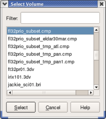
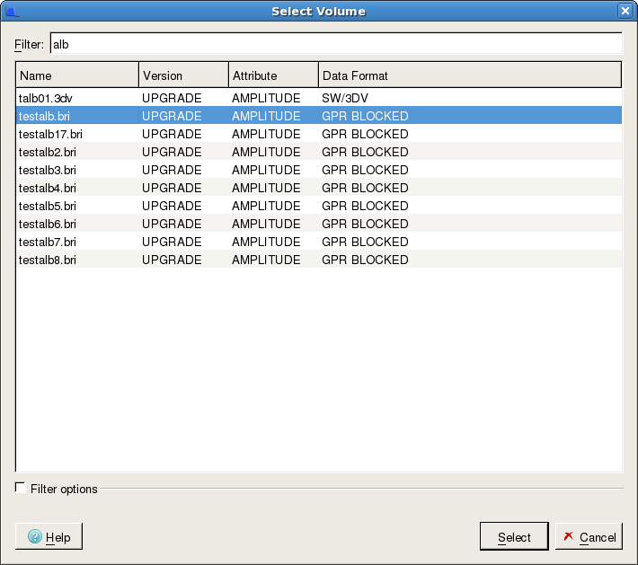
This section describes how you select the input volume for use by the "Apply Operator" module. Click the push button to the right of the Input field to pop-up the "Select Volume" dialog.
 ...
...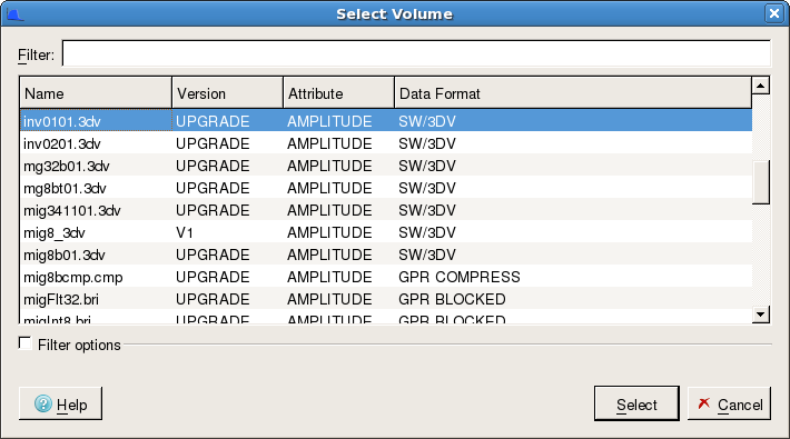
This dialog displays the available input seismic volumes betabetically ordered. As there may be many hundreds or even thousands of seismic volumes in your project a filter field has been provided. This field will allow you to supply a filter string. By supplying a filter string the list is immediately filtered to display only those seismic volumes which have the filter string anywhere in the seismic volume name. The wild card character * is also supported. (eg *mig*.bri). In the R5000 version the filter can be applied to any of the four columns by selecting the attribute to filter from the Filter column menu item.
Once you have located the input volume you can double click on it. This will select the volume and immediately close the "Select Volume" dialog and put the selected volume into the "Apply Operator" dialog Input field. Alternatively, you can select the volume with the mouse and then click the push button.
This section describes how you select the output volume for use by the "Apply Operator" module. Click the push button to the right of the Output field to pop-up the "Select Volume" dialog.
 ...
...
This dialog displays the available output seismic volumes betabetically ordered. Only seismic volumes previously written by an ARK CLS application will be displayed. As there may be many hundreds or even thousands of seismic volumes in your project a filter field has been provided. This field will allow you to supply a filter string. By supplying a filter string the list is immediately filtered to display only those seismic volumes which have the filter string anywhere in the seismic volume name. The wild card character * is also supported. (eg *junk*.bri)
Once you have located the output volume you can double click on it. This will select the volume and immediately close the "Select Volume" dialog and put the selected volume into the "Apply Operator" dialog Output field. Alternatively, you can select the volume with the mouse and then click the push button.
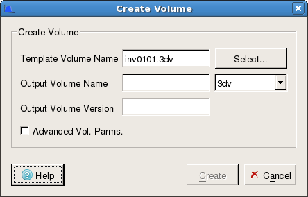
Frequently, it will be necessary to create a new seismic volume. This section describes how this is achieved. This process is easy, particularly if you accept the defaults. Click the push button to the right of the Output field to pop-up the "Create Volume" dialog.
 ...
...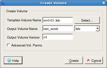
This dialog displays the various parameters required to create a new seismic volume. By default, the checkbox is turned off. In this mode, all you need to do is to select a template seismic volume, type in a name (and if OpenWorks R5000, a version) for the new volume and click the push button (see Create New Volume - basic parameters). If you need to modify the advanced volume parameters then tick the checkbox item. This will display additional parameters within three tabs: 3dv, Bricked and Compressed
Create New Volume - basic parameters
Template Volume Name: This item field allows you to select a template for the new volume via the push button. Any seismic volume can be selected, however, it is recommended that you select the input volume as this is likely to have the same areal extents.
Output Volume Name: This input field allows you to specify the name of the new seismic volume that is to be created. By default, the type of seismic volume to be created is set to be the same as the template. Again, it is recommended that you keep to the same type. If you wish to change the type of the new volume then use the combo box to the right of the "Output Volume Name" input field.
Figure 4.79. Create New Seismic Volume - Advanced Volume Parameters (.3dv Tab). 2003.12 (L), R5000 (R)
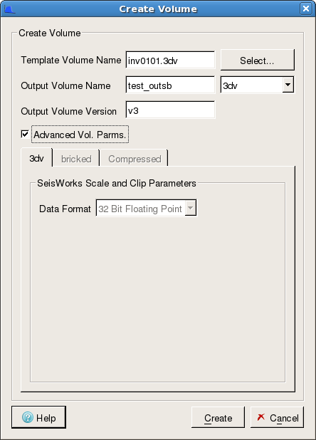 ... ... |
The image in the figure above shows the Create Volume dialog expanded to show the advanced volume parameters available for 3dv type via the 3dv tab. Note that for R5000 the Advanced Vol. Parameters have been simplified and that is now only possible to create 32bit output volumes.
Data Format: This item allows you to specify the data format of the output volume. Possible values are 32 Bit Floating Point, 32 Bit Integer and 16 Bit Integer.
Scaling mechanism: The Scaling Mechanism radio button is used to set parameters to control the conversion of seismic sample values stored in the 32 Bit Floating Point format used by Coloured Inversion to the requested SeisWorks output 3dv type. By default, the Scale and Clip Parameters frame will display scaling values as supplied in Landmark documentation. However, if the input SeisWorks 3dv class has been generated using our software, these defaults will be overwritten by scaling parameters read from our input class header file. Possible values are:
Sample * [supplied numerator] / [supplied denominator]
No Scaling
Max Only
Scaling using "Max Only" is the recommended method. Here data is scaled using the following formula:
(31 x 2(N-6))/MUA
where N is the Data Format (e.g. 16 for 16 Bit Integer) and MUA is the Maximum Unclipped Amplitude (i.e. the supplied amplitude value). An amplitude value is chosen which is representative of the maximum amplitude that is to be preserved (this is the MUA). It will be assumed that any amplitude values above this are not required. Choosing an MUA value might require you to analyse the data. This should be determined statistically, to exclude spikes and other outliers, such that normal amplitude values are less than or equal to the value set in the Amplitude field.
However, if is selected, each seismic sample value will be multiplied by the fractional scaler specified by the numerator and denominator in the text fields to the right. If is selected, the seismic sample values will be written to the output volume with no scaling.
Clipping Mechanism: This radio button item is used to control the clipping of sample values. Clipping is done after scaling and before the output data are written to disk. The possible values for the Clipping Mechanism radio button are , and Man Output Clip At. If is selected, then sample values exceeding the maximum permitted value for the requested Data Format (shown in the field to the right) are clipped to it. If is selected, then sample values will be written to the output volume without clipping. In this case, amplitudes exceeding the maximum permitted value for the requested output format will be aliased to a different lower value on output. This should be avoided as it will result in the generation of spurious data. If is selected, then sample amplitudes that exceed the value specified in the field to the right are clipped to it.
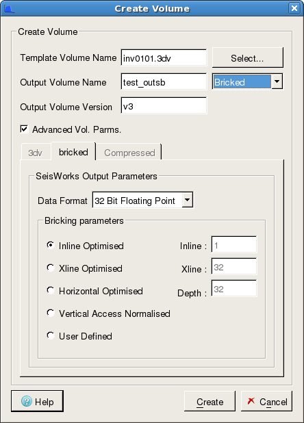
Figure 4.80. Create New Seismic Volume - Advanced Volume Parameters (Bricked Tab). 2003.12 (L), R5000 (R)
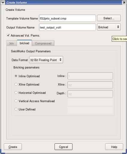 ... ...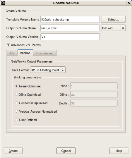 |
The image in the figure above shows the Create Volume dialog expanded to show the advanced volume parameters available for bri type via the Bricked tab.
Data Format: This item allows you to specify the data format of the output volume. Possible values are 32 Bit Floating Point, 16 Bit Float and 16 Bit Integer.
Bricking parameters: The possible values for the Bricking Parameters radio button are:
Inline Optimised
Xline Optimised
Horizontal Optimised
Vertical Access Normalised
User Defined
By default, the bricking parameter radio button is set to . If you select one of the top four options, the text fields to the right show the corresponding default brick sizes, but the fields remain desensitised. However, if you select the option, then the Inline, Xline and Depth fields to the right become sensitised, and you can specify your own brick dimensions.
Figure 4.81. Create New Seismic Volume - Advanced Volume Parameters (Compressed Tab). 2003.12 (L), R5000 (R)
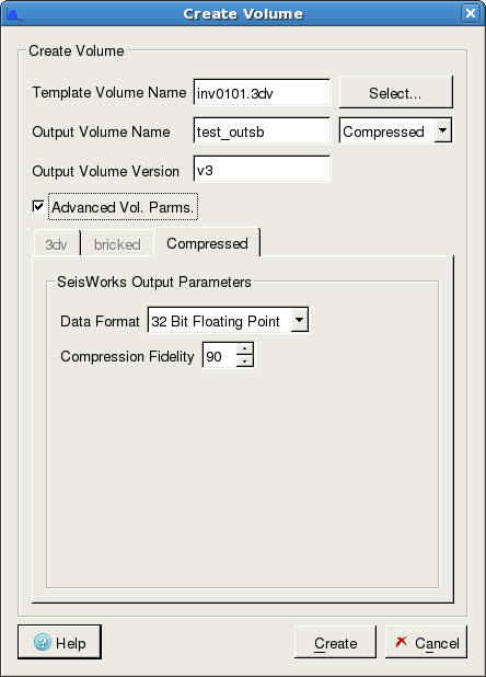 ... ... |
The image in the figure above shows the Create Volume dialog expanded to show the advanced volume parameters available for cmp type via the Compressed tab.
Data Format: This item allows you to specify the data format of the output volume. The only possible value is 32 Bit Floating Point.
Compression Fidelity: The possible values for the compression Fidelity are between 1 and 99.
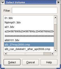
This section describes how you select the operator for use by the "Apply Operator" module. Click the push button to the right of the Operator field to pop-up the "Select Operator" dialog.
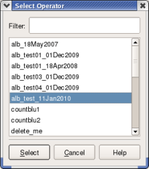
This dialog displays the available spectral blueing operators betabetically ordered. As there may be many hundreds of operators stored, a filter field has been provided. This field will allow you to supply a filter string. By supplying a filter string the list is immediately filtered to display only those spectral blueing operators which have the filter string anywhere in the seismic volume name. The wild card character * is also supported.
This section describes how you select the operator for use by the "Apply Operator" module. Click the push button to the right of the Operator field to pop-up the "File Selector" dialog.
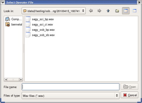
This File Selector dialog allows you to traverse the file system to select the colour inversion operator to be used. By default, the File Selector dialog only displays those files which have a file extension "wav". The File Selector dialog is the standard Qt File Selector which provides a considerable amount of functionality to filter and sort information about files in the viewed directory, which can help you select the operator.
This section describes how you specify the 3D survey area over which you will apply the spectral blueing operator. By default, the 3D survey area over which the operator will be applied, is the inline/xline extents of the input seismic volume. Note that when run in an OpenWorks R5000 environment there is a Survey parameter that should be selected before the Input volume.
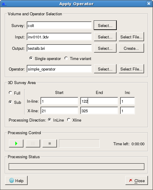
The 3D Survey Area block on the Apply Operator dialog to the left shows the controls available to you to restrict the 3D Area over which the spectral blueing operator is applied. This radio button control allows you to select the processing area mode. The possible values for this control are or . In area mode, the full extent of the seismic survey is used as input. In area mode, you must also supply the start inline, end inline, inline increment, start xline, end xline and xline increment in the corresponding controls. These controls only become sensitised when the mode is selected. The specified inline and xline values must be in the range of the input seismic data extent.
Start In-line: This input field control allows you to specify the start inline value. This must be within the range of the minimum inline and maximum inline of the selected seismic data. When you select an input seismic volume via the Input push button this field item is set by default to the minimum inline of that seismic volume, which corresponds to the processing area. When the adjacent 3D Survey Area radio button is set to , the Start In-line control becomes sensitised and you can reset this value if necessary. Automatic validation is performed to ensure that the specified value is within the maximum extent and that it is less than or equal to the End In-line control.
End In-line: This input field control allows you to specify the end inline value. The end inline value must be within the range of the minimum inline and maximum inline of the selected seismic data. When you select an input seismic volume via the Input push button this field item is set by default to the maximum inline of that seismic volume, which corresponds to the processing area. When the adjacent 3D Survey Area radio button is set to , the End In-line control becomes sensitised and you can reset this value if necessary. Automatic validation is performed to ensure that the specified value is within the maximum extent and that it is greater than or equal to the Start In-line control.
In-line Inc: This input field control allows you to specify the inline increment value N. This enables you to sub-sample the input seismic data by processing every Nth line in the inline direction. The inline increment must be set to a value between 1 and the maximum inline of the selected seismic data. By default, this field will be set to 1, which corresponds to the processing area. When the adjacent 3D Survey Area radio button is set to , the In-line Inc control becomes sensitised and you can reset this value if necessary. Automatic validation is performed to ensure that the specified value is set between 1 and the maximum number of inlines.
The description of the Start X-line, End X-line and X-line Inc input fields are the same as the Start In-line, End In-line and In-line Inc input fields but in the Xline direction.
Processing Direction: The Processing Direction radio button is used to select the order in which the input lines are processed. You can choose between a sequence of or processing. By default, the radio button is set to processing when the "Apply Operator" dialog is initially invoked.
This section describes how you start the processing within the "Apply Operator" dialog.
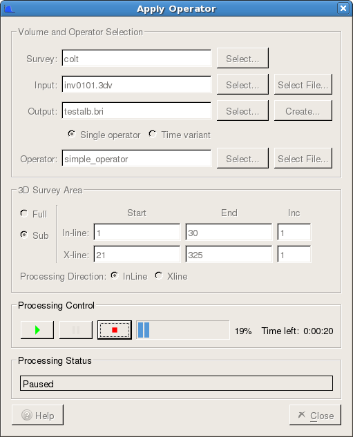
The "Processing Control" block within the "Apply Operator" dialog allows you start, pause or stop the processing. The image in the figure above shows the "Apply Operator" dialog after the processing has been started.
Start Processing: The  (start processing) icon is clicked to start the processing. When the "Apply Operator" dialog is first invoked this icon is desensitised and it remains desensitised until the required processing parameters have been selected via the Input Output or and Operator or push buttons. When you click the start processing icon an additional dialog will appear to prompt you to confirm that you wish to proceed with processing. Here you have the opportunity to confirm as some jobs run for a long time and will overwrite the output volume.
Pause Processing: The  (pause processing) icon is clicked to pause the processing. When the "Apply Operator" dialog is first invoked this icon is desensitised and it remains desensitised until processing has been set to run using the start processing icon. The pause processing icon remains sensitised during processing until it is itself selected or, until the stop processing icon is selected (see below).
Stop Processing: The  (stop processing) icon is clicked to stop the processing. When the "Apply Operator" dialog is first invoked this icon is desensitised and it remains desensitised until processing has been set to run using the start processing icon. The stop processing icon remains sensitised during processing until it is itself selected.
Processing Progress and Time remaining: To the right of the processing controls is a processing progress bar which shows the percentage complete. To the right of this is the Time left in hours, minutes and seconds.
This section describes the processing feedback that you get following the start of an "Apply Operator" processing run.
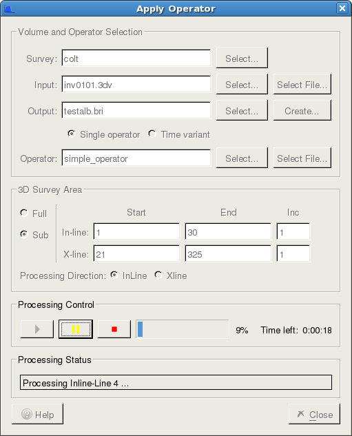
The Processing Status block within the "Apply Operator" dialog is located just above the and buttons. Its purpose is to provide you with processing status. Typically, this would say if the processing direction were Inline: "Processing In-line xxxx" where xxxx is the inline number currently being processed. Similarly, if the processing direction were Xline: "Processing X-line yyyy" where yyyy is the xline number currently being processed. Other status words are used as follows:
Paused - this status is displayed after processing has been paused by clicking the pause processing icon. It can be restarted by clicking the start processing icon.
Stopping - this status is displayed after processing is in the process of being stopped by you clicking the stop processing icon and confirming stop. This normally takes a few seconds whilst the processing module tidies up.
Stopped - this status is displayed after tidying has been performed following a request to stop after the stop processing icon has been clicked.
Done - this status is displayed after a processing run has completed successfully.